|
Firmware
0.8.0
|
|
Firmware
0.8.0
|
In this chapter, we set up a development environment that allows us to create the firmware, its unit tests, and the documentation. For this we install the Espressif IoT Development Framework (ESP-IDF) which, in addition to the obvious support for ESP chips, can also be compiled for Linux. This has the advantage that our unit tests can run directly on the host.
We recommend either an Arch (e.g. Garuda or Manjaro) or Ubuntu based distribution, so all of the following steps refer to those.
In order to start developing the firmware, we need to meet quite a few prerequisites. Fortunately, most of them can be obtained directly from the package manager. But before we do that, let's bring our system up to date.
Without going into detail about each individual dependency, the most important ones are CMake, a build system, GCC, a host compiler, Ninja, a build tool, Doxygen, a documentation generator, and Graphviz, a graph visualization software.
The ESP-IDF framework is the only dependency that we cannot get directly from the packet manager. Instead, we follow Espressif's instructions and clone the ESP-IDF repository into a directory called esp in our home directory.
GitHub allows you to clone a repository either over SSH or HTTPS. If you have the option, we recommend using SSH as we believe it simplifies commit signing.
Attentive readers will immediately notice that we have explicitly checked out version v6.0.2 here. We advise against using a different version than the one currently used by the master branch.
In addition to the ESP-IDF source code, the framework also requires some tools such as the Xtensa compiler or various Python packages. To set these up, Espressif provides an installation script that must be executed.
This script is available in different shell flavors. Please be careful to run the correct one.
It is optionally possible to build the Frontend from source while compiling the firmware. However, this requires the installation of Flutter. For more information please visit the Development section of the frontend documentation.
We generally recommend VSCode for development, but this step remains entirely optional. Feel free to otherwise fire up your favorite editor or IDE.
The firmware source code is also hosted on GitHub. As before, we can use either SSH or HTTP to clone the repository. Using git clone without any additional arguments will clone the latest version of the master branch to the current working directory. After that, we can change into the Firmware directory we've just created.
Before we can start building the actual firmware, we need to add the ESP-IDF framework and its tools to the PATH environment variable. For this, there is again a script available that needs to be sourced.
If everything has worked up to this point, Espressif will, after a series of debug outputs, reward you with the following message.
We'll try this out right away by starting one of three CMake build configurations. These configurations differ in the compiler's optimization level (Debug corresponds to -Og, Release corresponds to -Os), and above all in whether the USB peripheral is initialized as a built-in JTAG interface.
After the CMake configure stage has been successful, we just need to run the actual build stage.
The terminal output of our build tool tells us if the binary has been built successfully.
In order to flash the generated binary (or actually, binaries) onto a board, we need to put the board into the bootloader. This is done by
Afterwards we can use the flash command of the idf.py frontend to upload the firmware.
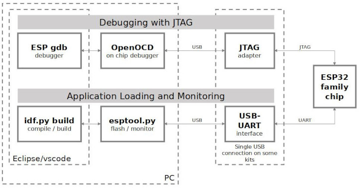
The idf.py frontend we just saw is only one of two ways to communicate with our ESP chip over USB. The other way is the built-in JTAG interface. Espressif's own documentation has a diagram that illustrates the two possibilities well. The convenient part is that both connections are made via the same USB cable. This is made possible by the ESP32-S3 chip itself, which provides two USB channels, one for JTAG and the other for the USB terminal connection we have already used.
Before we can establish a debugging connection with GDB though, we need to grant the appropriate rights to communicate with the OpenOCD device. To do this, we download the udev rules from Espressif's OpenOCD repository to /etc/udev/rules.d.
Since these udev rules use the plugdev group, it is necessary to add your own user to this group to avoid having to constantly debug as root.
With the udev rules installed, we can now start a debug session. We recommend using VSCode for this, but of course you can also do it manually via CLI.
VSCode To debug the firmware directly in VSCode, we install the GDB debugger extension Native Debug from the Visual Studio Marketplace. If you are not familiar with VSCode extensions, you can take a look at the official documentation.
Running the debugger is done by
A very useful feature of the ESP-IDF framework is the ability to run applications on the host. This allows us to write unit tests that do not need to be run directly on a board, but can be run on the host (and in the CI pipeline). The tests themselves are written with GoogleTest.
To build the tests executable we run the Tests build configuration.
And directly execute the .elf file.
If the optional prerequisites for building the docs were found during CMake's configuration phase, the FirmwareDocs target can be built to create the documentation.
If the build was successful, the website can be viewed simply with a browser by opening "build/docs/html/index.html" or by creating a small web server.